Abstract: IrDA is a standardized, wireless, infrared data communicaTIons method. Modern products often support RS-232 alongside IrDA, meeTIng legacy requirements. This applicaTIon note describes ways to achieve both interfaces with a single UART.
BackgroundThe term data-communicaTIons interface is ambiguous, but it can be resolved into three easily understood layers: the physical layer defines electrical characteristics and hardware communication speeds, the protocol layer defines the data format, and the application layer employs this data format to perform tasks in a given device. The application layer IrTran-P in IrDA, for example, is used in digital cameras and other imaging devices to transfer pictures.
RS-232 encompasses only the physical layer, but IrDA encompasses all three (physical, protocol, and application). IrDA includes several different physical layers: SIR (115kbps), MIR (1Mbps), FIR (4Mbps), and VFIR (16Mbps) . Because RS-232 and IrDA SIR use the same data framer (commonly known as a UART), this article considers only RS-232 and the IrDA SIR physical layer.
Because RS-232 has (until recently) been included in almost every computer for the last three and half decades, it is the most widely used physical layer in asynchronous serial communications. Most personal computers are replacing RS-232 with the Universal Serial Bus ( USB), but RS-232 remains common in network equipment, industrial-control equipment, and point-of-sale equipment (Table 1).
Table 1. Specifications important to the TIA / EIA-232-F physical layer
| Specification | Minimum | Maximum |
| Number of transmitters per data line | | 1 TX |
| Number of receivers per data line | | 1 RX |
| Cable length | | C <2500pF |
| Data rate | | 20kbits / sec * |
| Loaded Driver Output Range (0V Offset) | ± 5V | ± 15V |
| Maximum Driver Short Circuit Current | | 100mA |
| TX Load Resistance | 3kΩ | 7kΩ |
| Maximum Slew Rate | | <30V / us |
| RX Input Range | -25V | + 25V |
| RX Input Sensitivity | -3V | + 3V |
| RX Input Resistance | 3kΩ | 7kΩ |
* Despite this specification, some parts support data rates up to 1Mbit / sec.
The Infrared Data Association (IrDA) was formed in 1993, with the goal of defining a 3-layer interface that would allow communication among infrared appliances. IrDA SIR was established in 1994, and shortly thereafter Microsoft® added support for IrDA in Windows® 95 . IrDA is now available in equipment such as laptops, cell phones, digital still cameras, personal digital assistants (PDAs), and pagers. Table 2 lists some of the specifications important to the IrDA SIR physical layer.
Table 2. Specifications inportant to the IrDA SIR physical layer
| Specification | Minimum | Maximum |
| Transmit |
| Peak wavelength | 850nm | 900nm |
| Intensity in angular range | 40mW / Sr | 500mW / Sr |
| Half-angle | ± 15 ° | ± 30 ° |
| Data Rate | | 115.2kbps |
| Pulse duration @ 2.4kbps | 1.41us | 88.55us |
| Pulse duration @ 115.2kbps | 1.41us | 2.23us |
| Rise and fall time | | 600ns |
| Receive |
| Irradiance in angular range | 4uW / cm² | 500mW / cm² |
| Half-angle | ± 15 ° | |
| Receiver latency | | 10ms |
Traditional ApproachImplementing IrDA and RS-232 in a system with only one UART usually requires four ICs: a dual SPDT analog switch, an encoder / decoder (ENDEC), an RS-232 transceiver, and an IR transceiver (Figure 1). Table 3 suggests ICs suitable for the resulting circuit.
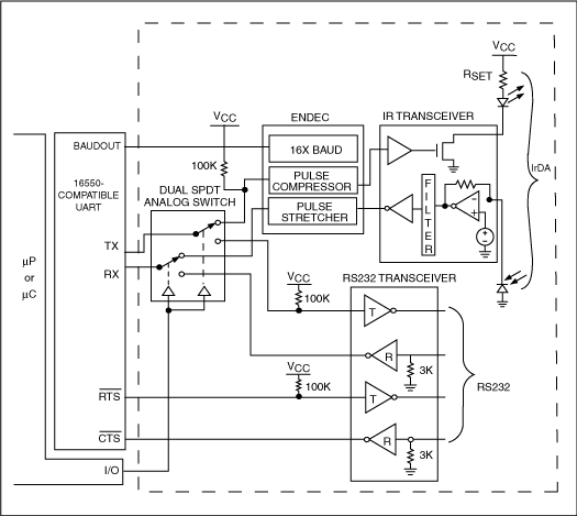
Figure 1. This traditional single-UART approach implements IrDA and RS-232 using four Ics.
Table 3. ICs for the 4-chip approach
| Dual SPDT Analog Switch |
| Maxim Integrated Products | MAX4567 |
| ENDEC |
| Agilent | HSDL-7000 |
| Texas Instruments | TIR1000 |
| RS232 Transceiver |
| Maxim Integrated Products | MAX232, MAX232A *, MAX3232E ** |
| IR Transceiver |
| Maxim Integrated Products | MAX3120 |
* Improved specifications
** Additional improved specifications.
The analog switch is controlled by the general-purpose output of a µP or µC, and directs transmit (TX) and receive (RX) signals to and from the corresponding transceiver. To meet the standard for IrDA SIR operation, the TX signal must pass through the encoder section of the ENDEC, which compresses the traditional UART NRZ signal to the single RZ pulse needed by the IR transceiver (Figures 2-3). The RX signal requires the opposite treatment, and is therefore routed from the IR transceiver into the decoder section of the ENDEC. The decoder stretches the single pulse to a traditional NRZ signal that can be recognized by the UART. The IR transceiver, then, transmits and receives information only in the infrared spectrum.
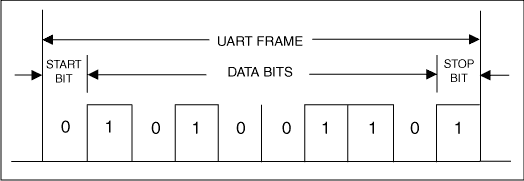
Figure 2. A UART frame before the encoder (pulse compressor).
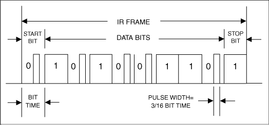
Figure 3. An IR frame after the encoder (pulse compressor).
More straightforward is RS-232 operation, in which the analog switch directs TX and RX signals to and from the RS-232 transceiver. Because RS-232 transceivers do not require an ENDEC, they can accept TTL / CMOS signals directly to and from the UART. An RS-232 transceiver is nothing more than a level translator, in which the TTL / CMOS levels are inverted, then translated to levels greater than + 5V and less than -5V using internal charge pumps. Alternative ApproachA popular alternative to Figure 1 eliminates the analog switch. This approach, which also implements IrDA and RS-232 in a one-UART system, requires only three ICs: an encoder / decoder (ENDEC), an RS-232 transceiver, and an IR transceiver. TX lines for the IR and RS-232 transceivers are connected together, thereby eliminating the need for an analog switch. Similar connections apply to the RX lines of both transceivers.
The common TX line delivers data to the IR and RS-232 transmitters simultaneously, but activating both transmitters simultaneously wastes power and is rarely required in an application. Many designers attempt to solve the problem by removing power from the unused transceiver electronically, but that arrangement is ineffective because the unused transceiver remains powered by voltage on the transmitter input line, via an internal protection diode. Thus, the alternative approach requires a careful selection of both transmitters, making it less foolproof than the traditional approach. You should therefore ensure that the IR and RS-232 transceivers in Figure 4 have a shutdown capability that is enabled without the need to remove power (Figure 4). Table 4 lists the ICs suitable for this circuit.
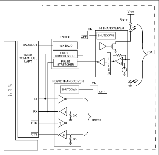
Figure 4. This alternative single-UART approach implements IrDA and RS-232 using three ICs.
Table 4. ICs for the alternative 3-chip approach
| ENDEC |
| Agilent | HSDL-7000 |
| Texas Instruments | TIR1000 |
| RS232 Transceiver |
| Maxim Integrated Products | MAX3222 |
| IR Transceiver |
| Maxim Integrated Products | MAX3120 |
Better ApproachThree or four ICs are no longer required to implement IrDA and RS-232 in a system with only one UART. Instead, the traditional circuit of Figure 1 can now be implemented with a single IC (Figure 5). That IC (MAX3130) contains the four necessary functions in a single 28-pin SSOP package. A logic signal applied to the active-low IRMODE pin controls an internal analog switch of the dual SPDT type. The switch directs signals to / from the RS-232 transceiver when high , and to / from the IR transceiver when low. The internal ENDEC compresses and stretches these signals with the help of a BAUD16 clock provided by the UART's BAUDOUT signal. Separate RS-232 and IR shutdown circuitry extends battery life in portable applications by turning off portions of the IC when not in use. The MAX3130 is more than equivalent to the 4-IC circuit of Figure 1, because it also includes edge-detect circuitry for monitoring activity on the unused interface.
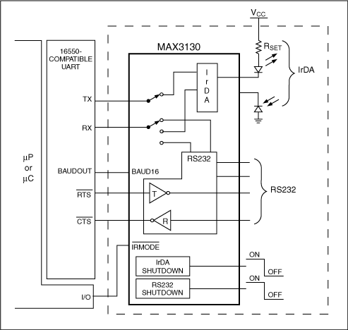
Figure 5. A better single-UART approach implements IrDA and RS-232 using only one IC. Improved Solutions to Other Common ProblemsMany of today's microprocessors and microcontrollers (µPs and µCs) include multiple internal UARTs, and a dual SPDT analog switch is not needed if two UARTs are available in the system processor. For such systems, the MAX3131 integrates an ENDEC, IR transceiver, and RS-232 transceiver with separate shutdown circuitry (no analog switch) in a single 28-pin SSOP package (Figure 6). That approach requires no µP I / O pin because it includes no analog switch to be controlled.
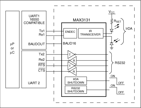
Figure 6. A better dual-UART approach implements IrDA and RS-232 using only one IC.
The UARTs internal to some µCs are unable to provide a signal equivalent to the BAUDOUT signal generated by the industry-standard 16550 UART. (The BAUDOUT signal is simply a clock that is 16 times faster than the selected baud rate.) All ENDECs require this Baud16 clock at some point, and creating such a clock for rates other than 9600 baud is no simple task. First, the Baud16 clock must be present before any communication, and the first communication is at 9600 baud. At that time the two connected IrDA systems agree on the fastest data rate to be supported by each system. The Baud16 clock must then be adjusted (increased) accordingly, to frame all new communications at the faster and current baud rate. You cannot simply divide down a crystal-oscillator signal with some flipflops and jumpers; the system must control the Baud16 clock through software.
Figure 7 shows a way to configure the MAX3100 and an existing SPI ™ port so the Baud16 clock can be modified through software using only one additional I / O pin (active-low CS2). As the world's smallest UART with an SPI front end, the MAX3100 can also generate a software-adjustable Baud16 clock via an SPI port. It looks odd, but the clock actually emerges from the MAX3100's active-low RTS pin. Figure 7 shows the MAX3100 sending a Baud16 clock into a MAX3131, but any other ENDEC IC requiring a Baud16 clock (including the MAX3130) will do as well.
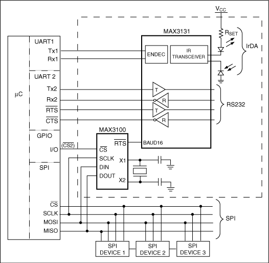
Figure 7. This MAX3100 circuit requires only one additional µC I / O to implement a software-adjustable BAUD16 clock generator.
Some applications require a separate UART for each communications interface, yet the designer may be compelled by cost or existing design constraints to settle for a µP with only one internal UART. That condition can yield a costly and complicated system. To make matters worse, the options run out fast if eight I / O pins are not available on the µP to interface to a second parallel hardware UART. Figure 8 shows how the world's smallest hardware UART (MAX3100) provides the second UART by interfacing to a 1P or 1C via an SPI port.
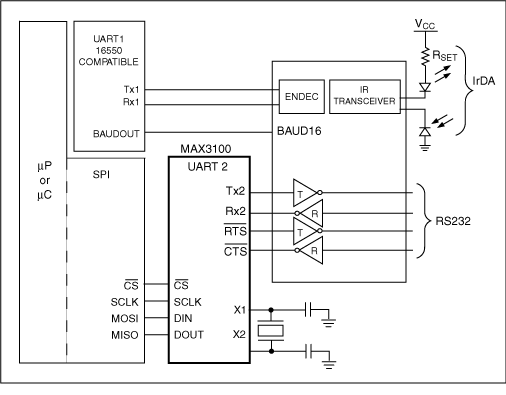
Figure 8. World's smallest hardware UART (MAX3100) interfaces to a microprocessor (or microcontroller) via a SPI port to provide a second UART. ConclusionIt is common for electronic equipment to contain more than one data-communications interface, and adding IrDA SIR to a device that already supports RS-232 can add convenience without adding much cost. On the other hand, adding RS-232 to a system that supports only IrDA makes that system compatible with additional types of equipment. Moreover, older systems that already support RS- 232 and IrDA are great prospects for an upgrade to reduce critical board space and cost. Thus, an understanding of how the blocks fit together and what your choices are can be quite helpful when designing RS-232 and IrDA SIR into a single piece of equipment . Definition of Terms Baud16: Name of a clock that is 16 times faster than the baud rate BAUDOUT: Output on standard UARTs producing a Baud16 clock CMOS: Complimentary Metal Oxide Semiconductor ENDEC: Encod er / Decoder IC: Integrated Circuit IrDA: Infrared Data Association IR: Infrared NRZ: Non-Return to Zero PDA: Personal Digital Assistant RS232: Recommended Standard 232 RZ: Return to Zero SIR: Serial Infrared SPI: Serial Peripheral Interface TTL: Transistor Transistor Logic UART: Universal Asynchronous Receiver Transmitter µC: Microcontroller µP: Microprocessor USB: Universal Serial Bus
Microsoft is a registered trademark of Microsoft Corp.
SPI is a trademark of Motorola, Inc.
Windows is a registered trademark of Microsoft Corp.
Inkjet Receptive Coating, Anticorrosion Pigments, Matting Agent